Fiber Orientation
Long Term Goals
- Establish a data structure for the quantification of Poly-3-hexylthiophene (P3HT) thin film morphology

Information from AFM Image That Matters
- Identifying fibers
- Fiber orientation
- Degree of crystallinity

Thresholding to 1. Identify fibers
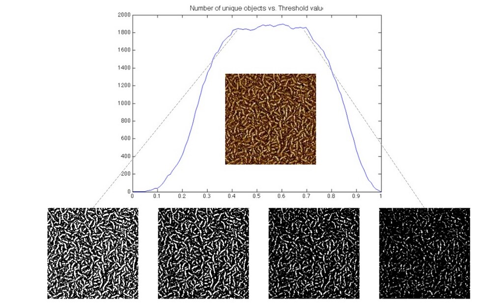
The thresholding post discusses our algorithm for finding the perfect thresholding value to isolate individual fibers. The following image shows a brief example of our work.

The result of such thresholding will be used to identify each fiber as a connected component. This can be used to find individual fiber orientation.
Ellipse fitting to find 2. Fiber orientation
regionprops was used to fit an ellipse to each connected component obtained from the previous thresholding to determine the orientation of that fiber.
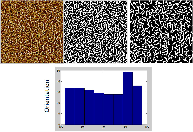
The following example is a proof of concept of finding orientations using regionprops. Of the AFM image(left) , we selected to only 5 components(center). The orientations of the components were accurately calculated and are displayed on the right.

The orientation detection along with thresholding is displayed below. Each pixel in the image identified as a fiber can be assigned one of 8 orientations.

Issues
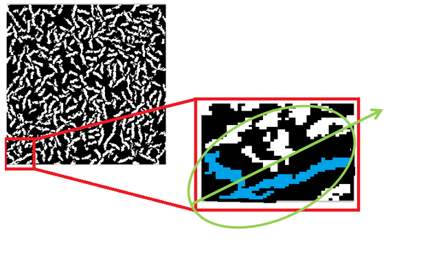
Overlapping fiber, especially those in completely different directions will contaminate the orientation calculation. The image below shows a case where the ellipse fit to the connected component in green will chose the green vector to calculate the orientation of the fiber. This orientation is incorrect for both fibers.

Possible solution:
Calculate the eccentricity of the ellipse fit the connected component and if the ellipse cannot possible belong to a single fiber, remove from orientation calculation. Use some other method to perform some sort of local orientation calculation.
Peak fitting to find 3. Degree of crystallinity
Expeimentaing with SciPy in Python. (Would prefer to use python for smooth work flow SwiftStack)